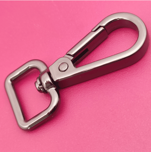
How to Make a new design metal Puller for bag
In the custom luggage hardware accessories industry, new product development often involves multiple rounds of drawing approval, prototype validation, and structural iterations. This is especially true for products developed without a physical reference—relying solely on images and dimensions—where discrepancies between design expectations and actual assembly results are common. This custom pull-tab project fully illustrates the custom product development process, from drawing approval, initial prototyping, structural revisions, and mass production to post-assembly adjustments.
Early Project Phase: Confirmation of Original Design Drawings and Development of the First Prototype
Drawing Preparation and Client Approval
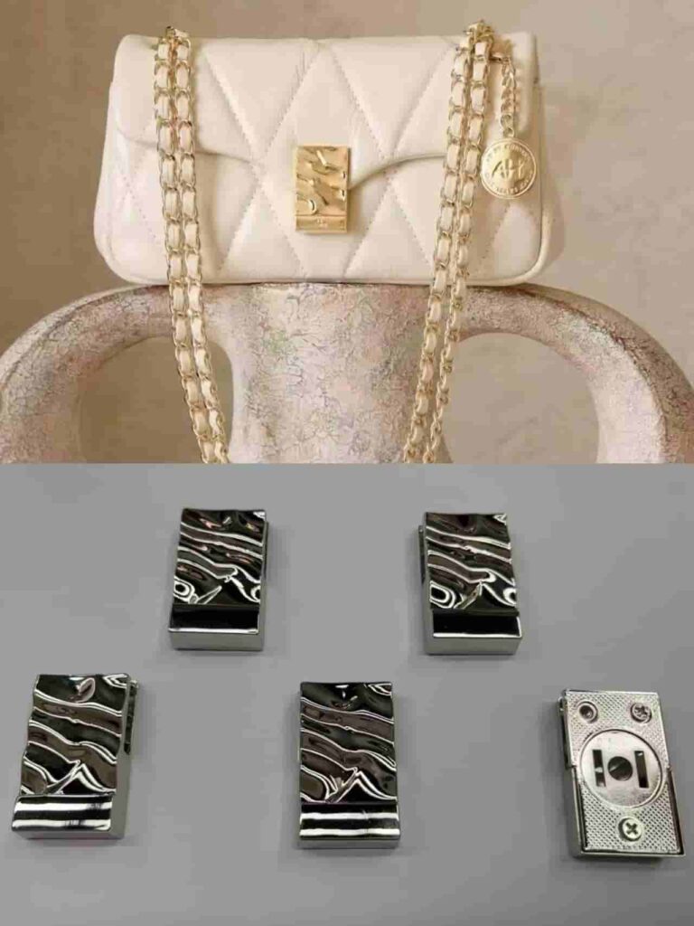
The client’s initial request was to create a 1:1 replica of a new zipper pull based on the provided images and dimensions, incorporating their own brand. There was no physical sample of the product—only image references and basic dimensions—and the thickness of the original design’s zipper pull varied between the head and tail.
Even though the client explicitly requested that the design and dimensions match the original images, we still followed standard procedures by creating engineering drawings based on the images and dimensions. We then resubmitted these drawings to the client for review and confirmation to avoid any misunderstandings caused by visual discrepancies in the images. Only after the client confirmed that the drawings were accurate did we proceed with the production of the prototype.
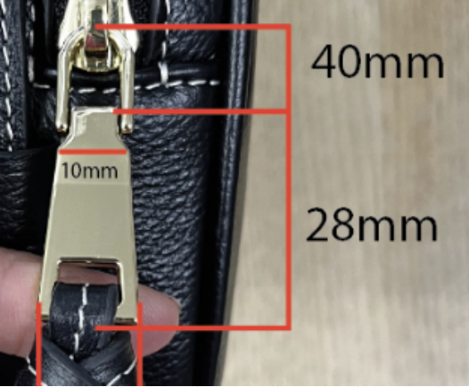 | 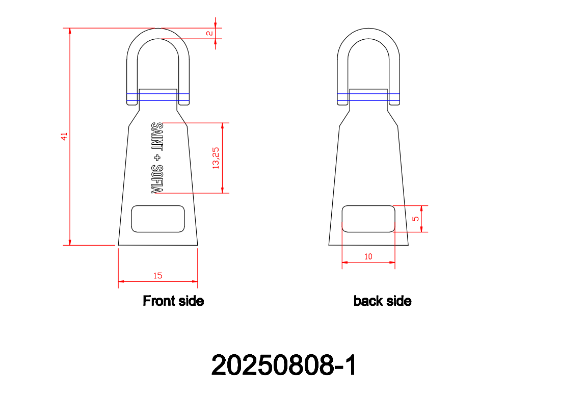 |
| original sample picture | artwork |
Production of the First Prototype and Customer Feedback
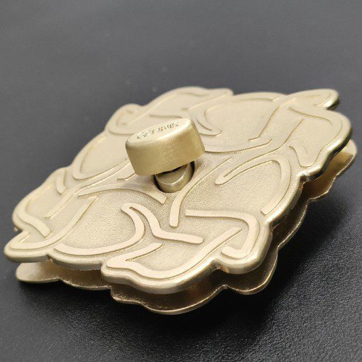
After we obtained the customer’s approval on the drawings, we arranged for the production of the first prototype and submitted it to the customer for review The prototype strictly adhered to the original design in the drawings, retaining the uneven thickness at the head and tail.
Upon receiving the physical prototype, the customer was dissatisfied with the original structural design. While they found it difficult to visualize the final product based solely on images, once we produced the physical prototype, they saw that the uneven thickness at the head and tail did not meet their expectations, so they requested revisions
Product Redesign: Confirmation of New Drawings, Sample Validation, and Production of the First Batch
Redrawing Drawings to Meet New Requirements
The client has provided new design requirements: the thickness at the beginning and end of the pull tab must be uniform, and there are significant changes to the structure and appearance, rendering the original drawings obsolete.
We redrew the engineering drawings according to the client’s new requirements, specifying the uniform thickness, logo placement, and specifications, and resubmitted them to the client for review. After the client approved the drawings, we proceeded to the prototype production phase for the new version.
New Sample Approved; Mass Production Begins
With the new drawings finalized, we produced the revised samples for the customer’s inspection. The samples met the requirement for consistent thickness from end to end, and the customer approved them.
After we obtained approval for the samples, we arranged for mold production and began mass production of the first batch.
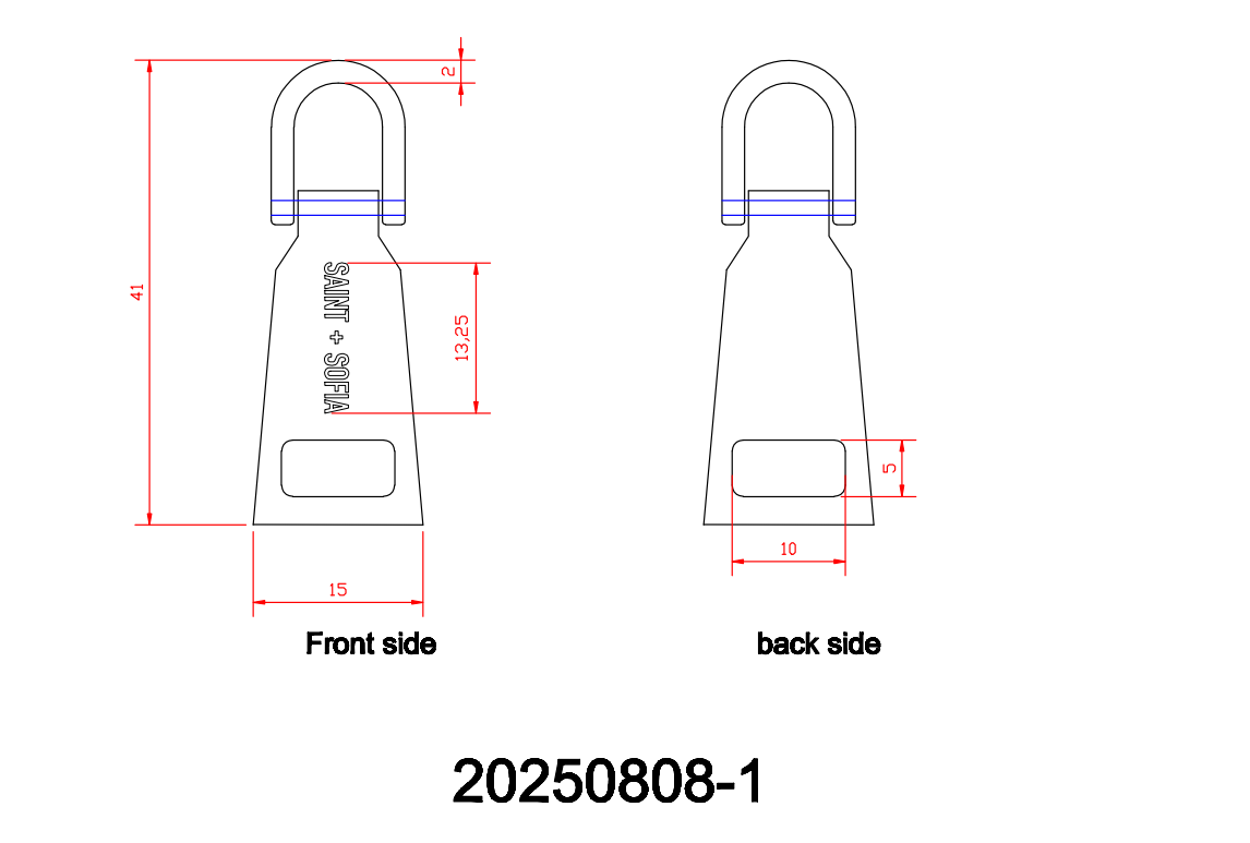 | 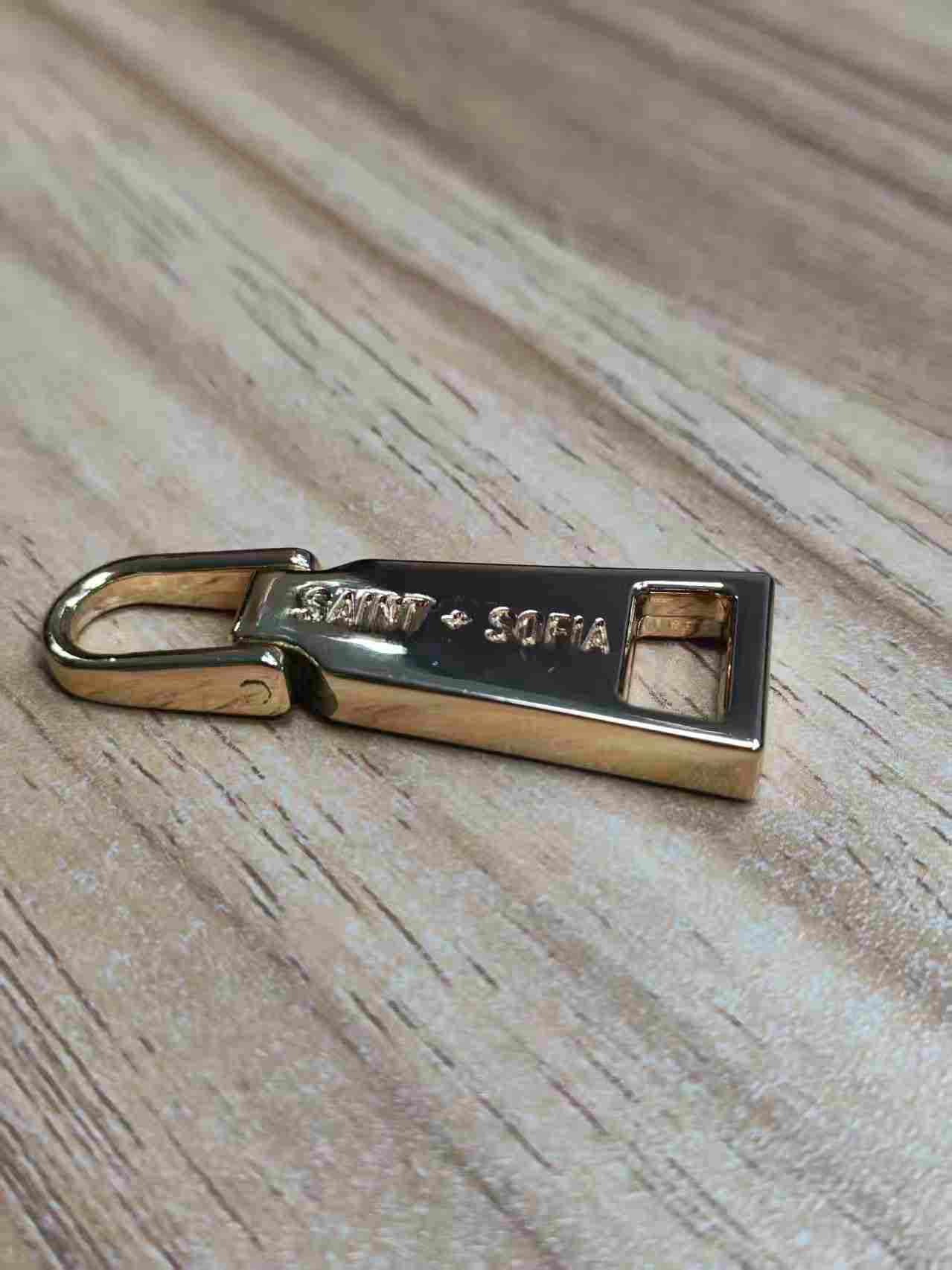 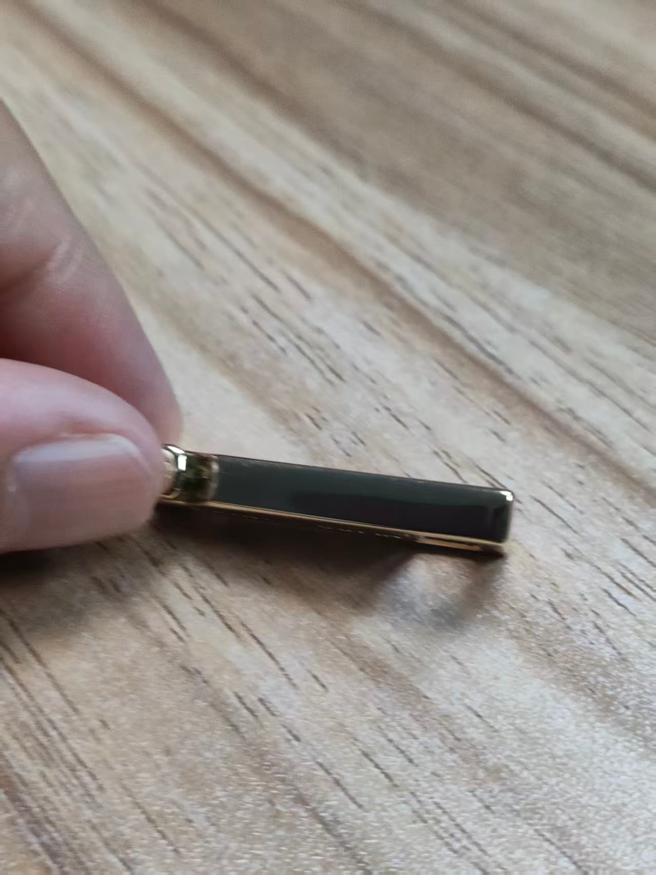 |
| new artwork for client | same thickness of new sample |
Assembly issue identified: the tab nose is too thick. Second revision and final mass production.
Dimensional Mismatch Issue During Mass Production Assembly
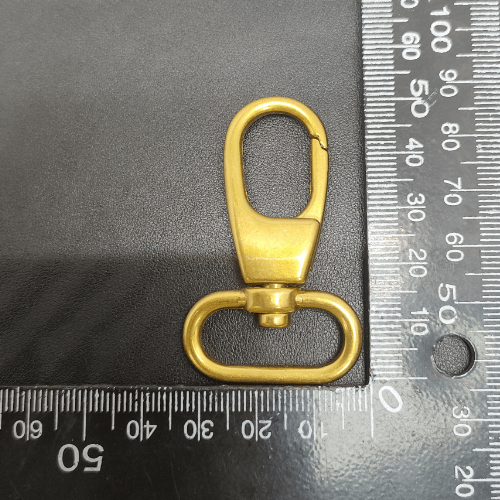
After the company delivered the first batch of mass-produced units and the customer put them into use, the customer reported assembly issues The tab nose had a thickness of 2.2 mm, but the opening and closing clearance of the corresponding slider was only 1.8 mm. Because the tab nose was too thick, it could not fit into the slider, so the workers could not assemble the product properly
Following discussions between both parties, they agreed on a corrective action plan: they would reduce the thickness of the pull tab nose to 1.6 mm to allow for an assembly clearance that accommodates the slider’s 1.8 mm opening space
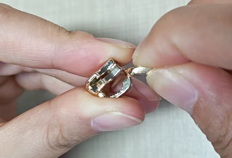 | 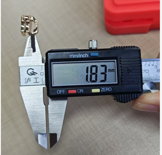 | 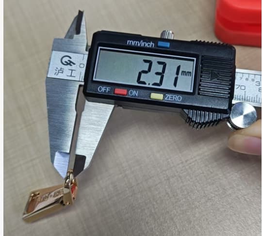 | 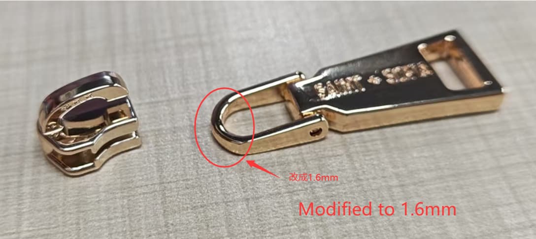 |
| The puller cannot be installed into the YKK slider | Slider gap: 1.8mm | the head thickness of puller is 2.3mm | Please modified to 1.6mm |
Confirmation of Drawing Revisions and Completion of Final Production Run
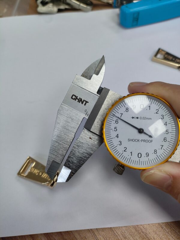
We adjusted the drawings and molds to accommodate a nose thickness of 1.6 mm. After completing the revisions, we submitted the revised design to the client for approval. Once the client approved the adjustments, we produced another set of prototypes to verify the assembly results.
After the prototype assembly tests passed, we immediately arranged for the final production run. The team successfully met the end-assembly requirements and finalized the project
Project Post-Mortem Summary
This slider development project fully demonstrated the characteristics of custom, non-standard product development: design renderings do not necessarily match the actual physical product, and drawing confirmation and prototype validation are essential steps. Even when a client insists on replicating the original design exactly, obtaining engineering drawings for confirmation in advance can help reduce misunderstandings between both parties.
At the same time, this project also highlights that, in addition to appearance and structure, product development must involve verifying the parameters of downstream assembly components in advance. The team failed to anticipate the installation clearance for the sliders in the early stages, causing dimensional conflicts that only came to light during mass production. For future new product development, in addition to confirming drawings and prototypes, we need to proactively collect assembly parameters for components and conduct assembly simulation tests in advance to reduce the cost of later mold modifications and improve project delivery efficiency.